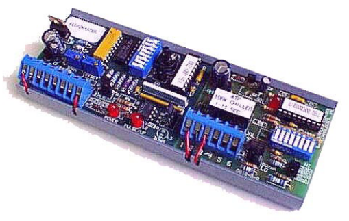
The 1st AIM1 interface powers the sensor from its 24 VDC terminal I1. The 4-20 mA loop powered sensor signal is fed back into terminal I2 and then into the 2nd AIM1 interface. The 1st AIM1 should be jumper shunt selected for current on both the input and output. A jumper wire is necessary between both interfaces on terminal I3. The 2nd AIM1 should be jumper shunt selected for a 0-5 VDC input signal. The 4-20 mA signal is converted to 1-5 VDC from the 1st AIM1 input impedance of 249 ohms. Both AIM1 interfaces will output a limited 4-20 mA signal, never going above 20 mA or below 4 mA. AIM1's on-board optical isolation feature allows isolated output signals despite shared common.