Here is the solution in detail.
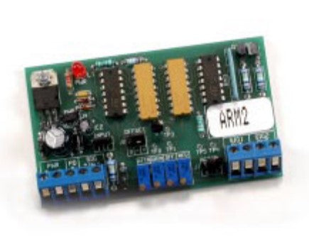
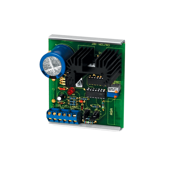
It requires the use of an ACI ARM (Analog Rescaling Module) interface.
The resistance signal is fed into the ARM as shown in the diagram below. In this example, we are using an input resistance of 500 ohms, but any other resistance range can be handled. Using power from the P terminal (a 20 VDC accessory power terminal), we wire that 30mA (maximum) driving current through the R1 resistor into the variable resistance R2. This voltage divider configuration allows the ARM to recognize a resistance signal change.
To set the minimum resistance signal to 2 mA output, you must adjust the ARM’s gain pot while inputing the minimum resistance. The following will assist in calculating the value of R1 based on any desired resistance input. We are using a 0-500 ohm input in this example.
P = 20 VDC
V in = 0-5 VDC
R2 = 0-500 ohms
R1=R2[ {20/5)-1] = 1500 ohm (this is the current limiting resistance)
To calculate the minimum wattage of the resistor required calculate the following:
I = E/R or P/(R1+R2)..or..20/(1500+500) = 0.01 amp (this is at maximum resistance)
Power = IE or .01 x 20 = 0.2 watts
I = E/R or P/R1...or....20/1500 = 0.013 amp (this is at minimum resistance)
Power = I x E...or...(.013) x 20 = 0.267 watts
...so required wattage needed for R1 should be 0.5 or greater.


