HVAC Supplies Blog

Posted by Adem Erturk on

Isolating a Loop Powered signal

Isolating a Loop Powered signal

The AIM1 offers a 24 VDC power output to allow a loop powered device to be connected directly to the AIM1. When the loop device is functioning, measure the voltage from I3 (-) terminal to I2 (+) terminal. The 4-20 mA signal generates a proportional 1-5 VDC across these terminals. This is an easy way to confirm proper connection and operation using Ohm's law. The AIM1 4-20 mA output signal will be completely isolated from the 4-20 mA loop input signal. The output signal will be limited to a maximum of 20 mA. The AIM1 shares the same common on the power supply and input signal.

See All AIM1 Products

Isolating a Loop Powered signal

The AIM1 offers a 24 VDC power output to allow a loop powered device to be connected directly to the AIM1. When the loop device is functioning, measure the voltage from I3 (-) terminal to I2 (+) terminal. The 4-20 mA signal generates a proportional 1-5 VDC across these terminals. This is an easy way to confirm proper connection and operation using Ohm's law. The AIM1 4-20 mA output signal will be completely isolated from the 4-20 mA loop input signal. The output signal will be limited to a maximum of 20 mA. The AIM1 shares the same common on...

Read more →


Posted by Adem Erturk on

How to convert a resistance to voltage or current?

How to convert a resistance to voltage or current?

We get many requests for a device to convert a resistance to voltage or current. This can be done very simply using ARM with voltage divider on the input. We can convert almost any resistive range to a 0-5 VDC signal which can be re-scaled by the ARM to any standard output. The ARM is also capable of re-scaling to most uncommon ranges also (reverse or direct acting).

Standard Outputs

  • 1-5 VDC, 0-10 VDC, 2-10 VDC, 0-15 VDC, 3-15 VDC, 0-20 mA, 4-20 mA.

Uncommon Outputs

  • 0-1 VDC, 4-7 VDC, 0-13 VDC, 2.406-3.868 VDC, 2.635-3.209 VDC, 0-5 mA, 0-10 mA, and many others possible.
Example 1 
Example 2

P = 20 VDC

Vin = 0-5 VDC

R2 = 1000 ohms (0-1000 ohms)

R1 = R2 [(P/Vin)-1]

R1 = 3000 ohms

I = E/R = P/(R1+R2) = 20/4000 =.005amp

Power = IE = (.005)(20) =.1watt

R1 wattage needed, .25 watt or greater

P = 20 VDC

Vin = 0-3.88 VDC

R2 = 135 ohms (0-135 ohms)

R1 = R2 [(P/Vin)-1]

R1 = 560 ohms

I = E/R = P/(R1+R2) = 20/560 =.028 amp

Power = IE = (.028)(20) =.56 watt

R1 wattage needed, 1/2 watt or greater

How to convert a resistance to voltage or current? The ARM provides a 20 VDC accessory supply voltage that is applied through the series (R1) resistor into the variable resistance output of a controller (R2). This is a voltage divider configuration that will apply a variable analog input into the ARM. It is important to use (R1) for heat dissipation and limiting current.

See All ARM Products

How to convert a resistance to voltage or current?

We get many requests for a device to convert a resistance to voltage or current. This can be done very simply using ARM with voltage divider on the input. We can convert almost any resistive range to a 0-5 VDC signal which can be re-scaled by the ARM to any standard output. The ARM is also capable of re-scaling to most uncommon ranges also (reverse or direct acting). Standard Outputs 1-5 VDC, 0-10 VDC, 2-10 VDC, 0-15 VDC, 3-15 VDC, 0-20 mA, 4-20 mA. Uncommon Outputs 0-1 VDC, 4-7 VDC, 0-13 VDC, 2.406-3.868 VDC, 2.635-3.209 VDC, 0-5 mA, 0-10 mA,...

Read more →


Posted by Adem Erturk on

What is zoned heating and cooling?

What is zoned heating and cooling?

Ahhh… air-conditioning and heating. They are probably two of the greatest inventions ever known to man when it comes to comfort. Feeling uncomfortably warm on a hot, summer day? All it takes is a few thermostat adjustments and you will be reveling in the coolness of your home. Freezing on a chilly, winter evening? No problem! Increase the warmth of your heater and be cozily toasty in your humble abode. With this, life looks easy especially if you live alone or in a single-story house. How about if you have two stories or more and you are sharing it with your family or friends? This can be a completely different story.


Have you ever heard of the “convection current”? If not, this is when hot air rises and cold air sinks. In homes, especially those that have two floors or more, having certain cold spots or warm spots is not a surprise anymore, even if there are heating and air-conditioning. When it comes to our homes, we want them to be as optimally comfortable as possible, which is why it blows to have these spots. However, there is no need to fuss anymore because now, we have zoned heating and cooling!


Zoned heating and cooling

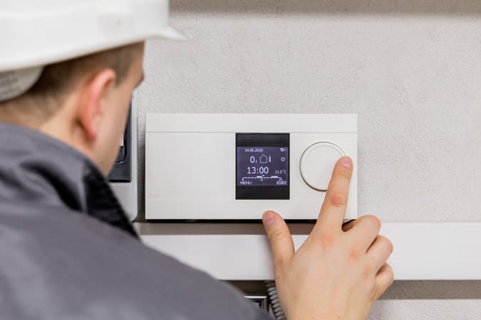
If you do not know what is zoned heating and cooling just yet, don’t worry because it’s not too late. Zoned heating and cooling is a system that divides your home into various areas and is managed distinctly by a thermostat. In other words, doing so allows you and the people you live with to enjoy each room at preferred temperature levels without affecting each other’s comfort.
Without zoned heating and cooling, rooms on the first floor of your home will generally feel colder compared to rooms in the upper floors even if you have installed heating and air-conditioning all over your house. While people downstairs may be chilling with the temperature that they like, you may feel warmer than them when you are in your upstairs bedroom.


Zoned heating and cooling operate through electric zoning (HVAC) dampers that go through your home’s air ducts. So how do HVAC dampers work?


HVAC dampers are valve-like mechanisms that control the flow of air temperatures through your house. What controls the HVAC dampers are the different thermostats that are installed in the various areas of your home. This is what makes it possible to have varied temperatures in each room and allows you to adjust them to you and your family’s liking.


When you set your room thermostat at either warmer or cooler temperatures, it sends a signal to your home’s HVAC dampers to open and bring in more hot or cold air. By the time your room reaches your desired temperature, your HVAC dampers will close and continue to distribute air to other parts of your house. How HVAC dampers work is the same with how traffic officers do their job. Case in point, they help regulate the distribution or movement of both hot air and cold air within your home.


Having zoned heating and cooling for your home is such a nifty feat, right? If you already have HVAC, but don’t have dampers yet, you can either install them by yourself or call the professionals to do it for you. If you are the kind who likes to do do-it-yourself projects, then here’s a guide on how to install HVAC zone control dampers.


How to install HVAC zone control dampers

Before doing anything, you must first carefully plan for the installation of your HVAC zone control dampers. It is important to know the ideal locations for these which is why you need to examine your air ducts and your furnace to identify where to place them. Once you have properly identified where to position your dampers, you can now get ready and start the installation.

How to install HVAC zone control dampers

Here are the materials that you will need:

  • Damper to be installed
  • Drill (preferably cordless)
  • Safety glasses for protection
  • Shears
  • Wire (size depends on the size of the damper you are working on)
  • Aluminum duct tape
  • Wire nuts
  • Marker

Now, let’s get started with installing HVAC zone control dampers!

  1. Using the marker, indicate the area where you will cut the air duct. Also, use this to measure the size that you need to cut out from the air duct.
  1. Take out the section of the air duct where you plan to install it in. Next, with your shears, cut out a part where you plan to install the HVAC zone control damper on.
  2. Put the section you took out earlier to back to the rest of the air duct you removed it from and set up the damper in the middle.
  1. Your HVAC damper comes with a junction box. Put this on top of the electrical wires on your damper.
  2. Attach the wires to the appropriate power source and make sure to follow the manufacturer’s instructions. Also, remember to keep your connections grounded.
  1. Using the provided sheet metal screws, secure the damper on both ends. Stick aluminum duct tape on the seams to close it up.


As long as you do it correctly and you are careful, installing an HVAC zone control damper should be a piece of cake. Once you do this, not only will your home be more comfortable, but you will also be able to save more energy. Having a zoned heating and cooling system is also friendly on your pockets! As a quick note, if you want to optimize the use of your HVAC damper, think about setting up either single or multi-zone controllers.


For your HVAC zone control damper needs, Black Hawk Supply can take care of that for you! We are a privately held small business located in the Midwest. With over 30 years of experience in the HVAC controls industry, we ensure you only the best quality products for your heating and cooling needs. Let us help you bring more comfort to your home. Contact us at (847) 773 0645 or shoot us a quick e-mail at cs@blackhawksupply.com and we will be more than happy to assist you!
What is zoned heating and cooling?

Ahhh… air-conditioning and heating. They are probably two of the greatest inventions ever known to man when it comes to comfort. Feeling uncomfortably warm on a hot, summer day? All it takes is a few thermostat adjustments and you will be reveling in the coolness of your home. Freezing on a chilly, winter evening? No problem! Increase the warmth of your heater and be cozily toasty in your humble abode. With this, life looks easy especially if you live alone or in a single-story house. How about if you have two stories or more and you are sharing it with...

Read more →


Posted by Adem Erturk on

7 Reasons of Undesired Oscillations in Pneumatic Systems

7 Reasons of Undesired Oscillations in Pneumatic Systems

Oscillation, if it occurs, may be in the form of a sputter, “motor boat”, pop, click, or hiss as the interface is modulating pressure up or down to achieve set point. Some reasons are as follows:

1. CAPACITY

Not enough branch line capacity. The minimum requirement for the pneumatic interface is two cubic inches of branch line volume. Without the required capacity the pressure can change faster than the valve(s) can respond.

2. LEAKS

Excessive branch line leaks can be caused by:

  • a. Gauge port leak.
  • b. Controlled device bleeds too much (i.e. Receiver Controller).
  • c. Branch line connections leak.
  • d. Debris, oil or water contamination in interface valve.
  • e. Leak around orifice.
  • f. Leak in interface valve.
  • g. Leak in manifold.
  • h. Transducer gasket missing or misaligned.

3. INPUT SIGNAL

AC line noise induced onto input signal.

4. POWER

Power supply voltage too low or fluctuates too low.

5. PRODUCT DEFECTS

  • a. Defective valve.
  • b. Defective manifold.
  • c. Incorrect calibration (someone has tampered with trim pots).
  • d. Defective circuit.

6. MAIN AIR PRESSURE

Main pressure is too high or erratic

7. ENVIRONMENT

  • a. Excessive vibration.
  • b. Water or condensation in air supply.
7 Reasons of Undesired Oscillations in Pneumatic Systems

Oscillation, if it occurs, may be in the form of a sputter, “motor boat”, pop, click, or hiss as the interface is modulating pressure up or down to achieve set point. Some reasons are as follows: 1. CAPACITY Not enough branch line capacity. The minimum requirement for the pneumatic interface is two cubic inches of branch line volume. Without the required capacity the pressure can change faster than the valve(s) can respond. 2. LEAKS Excessive branch line leaks can be caused by: a. Gauge port leak. b. Controlled device bleeds too much (i.e. Receiver Controller). c. Branch line connections leak....

Read more →


Posted by Adem Erturk on

8 Tips on Operating a Pneumatic Interface

8 Tips on Operating a Pneumatic Interface

  1. Main air pressure must be maximum of 25 psig.
  2. Branch volume should be at least 2 cubic inches.
  3. If the controlled device bleeds air, then a PXP0.3 or PWP0.3 interface is suggested.
  4. Seal any leaks in the branch line.
  5. Blow out any loose contamination from the orifice that might be blocking air.
  6. Apply teflon tape to gauge or plug to prevent air leakage.
  7. If the pneumatic interface "LEAKS", increasing branch line pressure, hold a finger over the bleed orifice and input a low signal. If pressure starts increasing:
    • a. Remove the branch line
    • b. Power up unit and give a maximum signal
    • c. Place finger over branch port and tap for a couple of seconds. This could allow any debris to be blown out.
    • d. Replace air lines and retest.
  8. If the pneumatic interface "LEAKS ", decreasing the branch line pressure, hold a finger over bleed orifice & input a high signal. If the pressure starts decreasing:
    • a. Pinch branch line tubing. If pressure is stable, then check for leaks beyond the interface in the branch line
    • b. If pressure is still decreasing, then check at the interface
      1. Remove both air lines
      2. Place main air on branch port
      3. Tap finger over the exhaust hole for a few seconds. This could allow any debris to be blown out)
      4. Replace air lines and retest.
8 Tips on Operating a Pneumatic Interface

Main air pressure must be maximum of 25 psig. Branch volume should be at least 2 cubic inches. If the controlled device bleeds air, then a PXP0.3 or PWP0.3 interface is suggested. Seal any leaks in the branch line. Blow out any loose contamination from the orifice that might be blocking air. Apply teflon tape to gauge or plug to prevent air leakage. If the pneumatic interface "LEAKS", increasing branch line pressure, hold a finger over the bleed orifice and input a low signal. If pressure starts increasing: a. Remove the branch line b. Power up unit and give a...

Read more →